CSV Optional Features
Standard Control
The standard Cycle Stop Valve maintains a constant pressure downstream of the valve, has a built in minimum flow to properly cool the pump and motor, which also determines the fill rate of the pressure tank. Consult the factory when more than 125 PSI differential pressure is required.
Multiple Valves for High Differential Pressures
A single Cycle Stop Valve can handle up to 125 PSI differential pressure. When there is more than 125 PSI differential, as happens with deep wells that have a high static water level, more than one CSV can be used to stair step the pressure down. For example; If there is 300 PSI inlet pressure to the CSV, valve #1 is set at 175 PSI, which leaves 125 PSI difference. Then valve #2 sees 175 PSI coming in, and can be adjusted to 50 PSI out, which leaves only 125 PSI differential pressure for this valve as well. Sometimes even a third valve can be used if inlet pressures are higher than 300 PSI. Consult the factory for help in these situations.
Dole Flow Valves
CSV's can work in conjunction with a Dole flow regulator valve. Attached to the line before the CSV, the Dole flow valve limits the maximum flow that the pump can produce. The CSV installed after the Dole valve, then regulates flow from the maximum allowed by the Dole valve, to the minimum flow rate built into the CSV. The CSV maintains a constant pressure when the flow demanded is between the maximum flow controlled be the Dole valve, and the minimum flow controlled by the CSV. The Dole valve can prevent the pump from being able to over pump the well, while the CSV still delivers variable flow and constant pressure at lower flow rates.
Multiple Pressure Settings
2" and larger Cycle Stop Valves are piloted operated. Pilot operated valves have a multitude of possible options. The CSV can have more than one pressure reducing pilot control. Each pilot can be adjusted to a different required pressure, and can be switched between these different pressures manually, or with an electric solenoid. This enables the CSV to operate at a lower pressure when low flow rates are required, and higher pressure when larger flow rates cause additional friction loss in the pipeline. Cycle Stop Valves have been equipped with as many as 5 regulator pilots and solenoids, when 5 different pressure setting were required for different purposes.
Back Pressure Control
In addition to the pressure-reducing pilot that controls the downstream pressure, the CSV can also be equipped with an additional backpressure pilot, to control the upstream pressure. A back pressure pilot can be used to hold a certain pressure on the pump, to prevent the pump from overloading, pumping a well dry, or eliminate cavitation, even when someone opens too many outlets in the distribution system, or when filling empty pipe lines.
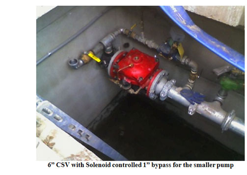
Additional Bypass Flow, with or without Solenoid
When a CSV is used with very large pressure tanks and water towers, or on large pump systems without a Pressure Maintenance pump, the average 5 GPM bypass built into the CSV may need to be increased. An additional and external bypass pipe can be installed from the inlet to the outlet of the CSV. This external bypass can use a ball valve or Dole valve to regulate the larger required minimum flow rate. Additionally, an electric solenoid can be used to open and close the extra bypass line as needed. An example would be two submersible pumps, hanging in the same well, using a Wesley Tool. A single 6" Cycle Stop Valve is used with an external bypass line capable of 50 GPM. When the large pump in the well is running, the solenoid controlling the external bypass is opened, allowing a 50 GPM minimum, while the small pump is shut off. When demand decreases below 50 GPM, the system pressure builds, and the pressure switch shuts off the large pump. At the same time the small pump is started, and the solenoid is closed, reverting the small pump back to the normal 5 GPM bypass that is built into the CSV. When the demand increases above 50 GPM, the small 50 GPM pump can no longer maintain the required pressure. As the system pressure decreases, a pressure switch starts the large pump, shuts off the small pump, and reopens the 50 GPM bypass. This allows a large pump, small pump combination to be installed in the same well, use the same drop pipe, and the same Cycle Stop Valve.
Deactivate CSV to eliminate friction loss
In some cases where the size of the pump is marginal, the 7 PSI friction loss through the CSV during maximum flow can be almost completely eliminated. Closing off the 1/4" line that feeds the top bonnet of the CSV, and removing a plug on the upper bonnet, will turn the CSV into a piece of pipe. The few cups of water that are in the upper bonnet will come out the open hole, and the CSV will be in the fully open position. The friction loss of the CSV will be the same as in the chart for a fully open valve. This can be accomplished manually by removing the tube to the upper bonnet of the CSV, and plugging the hole in the pilot regulator valve. Or two 1/4" ball valves can be installed. One ball valve is needed to close off the line from the pilot, and another to open line from the bonnet to atmosphere. Solenoid valves can also be used instead of ball valves, to automate this operation.
To fully open a CSV that is working with a pressure switch and pressure tank, an electric Three Way Valve can be installed on the CSV. This Three Way Valve can be electrically activated with it's own pressure switch. When activated, this Three Way Valve Closes off any control flow to the CSV, while dumping a small amount of water to atmosphere. This causes the CSV to open completely, which eliminates almost all the friction loss from the CSV. When the system pressure increases, the additional pressure switch deactivates the Three Way Valve, and the CSV returns to normal operation.
CSV works with pumps powered by Diesel or Gas
A CSV will deliver constant pressure and variable flow from Engine Driven pumps as well. The only consideration is to make sure and use a Governor on the engine. When the CSV reduces the flow rate, the horsepower to the engine will be reduced. Over-speed may occur without the use of a Governor.
CSV works with VFD
As long as the VFD will still run the motor at full speed, you can convert it to an electronic soft start. With some Drives you can use the two wires from the pressure transducer directly on a standard pressure switch. Other drives will have a place for two wires from a switch or pilot control and the transducer wires are just disconnected. You will have to read the wiring diagram for the particular Drive to determine which two connections to make to a pressure switch. Then if possible you want to program the Drive to ramp up within 2 to 3 seconds. Install a Cycle Stop Valve on the discharge of the pump and tee off to a small bladder tank with the pressure switch as per normal Cycle Stop Valve instructions. Adjusting the Cycle Stop Valve and pressure switch as per normal instructions will vary the flow and maintain a constant pressure. The pressure switch adjustment can be according to the size of tank installed. Later on when the drive completely fails you can easily switch over to a standard across the line starter or another soft start. I find the old style Auto Transformer type soft start panels to be more reliable than electronic soft starters if you can find one.
A CSV can also work on systems with a VFD and multiple pumps. Set the CSV and the on setting of the pressure switch 10 PSI lower than the pump with the VFD. Also set the off setting of the pressure switch at the same pressure as the operating pressure of the VFD controlled pump. The CSV controlled pump will only come on when the VFD controlled pump cannot keep up with demand or trips out. The CSV controlled system can also be set 10 PSI higher than the operating pressure of the VFD system. In this way the VFD controlled pump is secondary.
Two Pumps in the Same Well (Wesley Tool)
To put two pumps in the same well where the casing is not large enough for two pumps to hang side-by-side, you will have to use a Wesley Tool. This adapter allows you to hang both pumps on the same drop pipe. The smaller pump will hang on the drop pipe above the larger pump. The 4" Cycle Stop Valve (CSV) and plumbing at the top of the well is the same as a normal installation with one exception. You will need to install a 1.25" by-pass around the CSV with a solenoid valve and a ball valve. This by-pass allows us to set the minimum flow for the larger pump so it will allow this pump to shut off when the flow can be handled by the smaller pump.
Typical settings will be as follows. Pump#1 (7.5 HP) pressure switch settings ON 70# Off 80# with low pressure cut off switch set at 55#. Pump #2 (75 HP) pressure switch settings ON 65# Off 85# with low pressure cut off switch set at 55#. The pressure tank should be pre-charged to 50# and the pressure relief set at 90#. With these settings this is how it will typically work. The pumps are in a no flow condition and you start using 15gpm. The pressure in the pressure tank drops from 80# to 70#. At 70# the pressure switch for pump #1 starts the 7.5HP submersible. The CSV is set at 70# and the valve regulates and holds 70# steady. The CSV will hold this pressure until the system uses more water than the 7.5HP can provide which is approx. 45-50 gallons . When more than 50 GPM is being used the pressure drops to 65# and the pressure switch for the 75HP closes which starts the 75HP pump. When the 75 HP starts a relay will cut out the 7.5HP and energize the solenoid on the 1.25" by-pass, which will be set to flow 30gpm. The system was requiring over 50gpm when the pressure dropped enough to start the75HP. The minimum flow through the bypass and CSV is now 35gpm. Because system usage is over 50 gpm the CSV will hold the system pressure at 70#. When the system usage drops below 35gpm the bypass will allow the 75HP to build pressure to 85psi and the pressure switch shuts off the 75 HP pump. Since there is still usage in the system the pressure will quickly drain the tank down from 85 psi to 70psi and the 7.5HP will come on and take care of the low flow conditions.
System settings overview
- Cycle Stop Valve set at 70psi
- Pressure tank pre-charge 50psi
- 7.5HP Pump #1 Pressure switch On 70psi Off 80psi
- #1 Low pressure cut off set at 55psi
- 75HP Pump #2 Pressure switch On 65psi Off 85psi
- #2 Low pressure cut off set at 55psi
Additional Features
There are more than 2500 different features, and combinations of features, available for any pilot operated Cycle Stop Valve. When different or unusual conditions exist, the CSV can be modified to handle a multitude of different functions. Although we try to keep the operation of the CSV as simple as possible, the possibilities are limited only by your imagination. If you have an idea that is not listed above, please give us a call.