CSV3R: Installation Instructions
Note: Submersible motor manufacturers recommend using a flow inducer sleeve to be sure the motor is sufficiently cooled at low flows. Pressure differential across the valve cannot be more than 125 PSI.
Please read all instructions before installation
Installation
- Be sure that well has been pumped clean before any valve installations. It is also important that all lines including the pump, be flushed clean of debris. Turn off power to pump and drain system. This product creates back pressure, that is how it works. Back pressure is determined by the pump you are using. Be sure your piping between the pump and the Cycle Stop Valve is rated for that pressure.
-
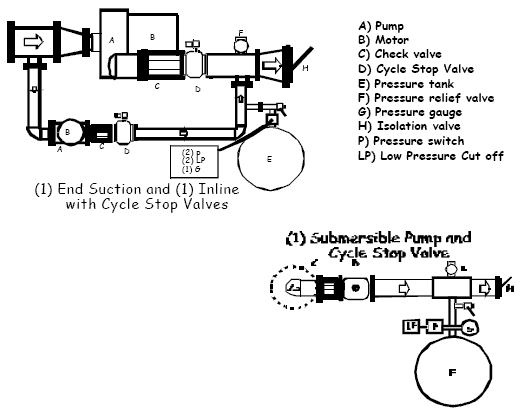
When installed horizontally, the valve should be positioned with the "loading" port facing up. If installed vertically, the flow direction arrow must be facing up. The CSV3R should be installed on the pump side of the pressure tank/pressure switch with all water outlets downstream of the valve. Flow direction is indicated with the arrow on the side of the valve.
Note: There cannot be any water outlets between the pump and the valve. If outlet lines exist between the well and the tank, the valve must be installed at the well head.
- Pressure tank should be installed on a tee at a 90° angle to the main discharge line downstream of the CSV3R. Pressure tank precharge should be 5-10 psi lower than the pressure switch start point. A water line at least 8" and no larger than tank discharge size (1 1/4" at the largest) should be used to connect tank. Pressure switch and other controls must be installed as close to tank as possible. Pressure switch should not be installed directly on the main line, but on the small line close to the tank.
- For start up, loosen lock nut on adjusting stem of pilot valve. Make sure adjusting stem is loosened completely. (It does not hurt to remove adjusting stem.) Set your pressure switch to desired pressure settings. Shut off pressure must be at least 5 PSI higher than valve set pressure. (ie..pressure switch cut on 60 psi, valve set at 60 psi, pressure switch shut off at 65 psi or higher) Open a small water outlet. Turn pump on. It is critical that you allow no more than 6-10 GPM past the valve during the setting procedure ( approximately 1 standard 3/4" water hose). Adjust the CSV3R to desired pressure by turning the adjusting stem on the pilot clockwise to increase pressure, and counterclockwise to decrease pressure. When pressure steadies at the desired system pressure, tighten the lock nut on adjusting stem on the pilot.
- Close off the water outlet, making sure no water is being released to the system. The pressure tank will begin to fill. As pressure tank fills, pressure in the system will slowly increase. When the cut off pressure is reached, the pump will be shut off. Pressure switch shut off point must always be at least 5 PSI higher than the pressure regulated by the CSV3R. Actual pressure switch settings depend on the size of the tank used and run time needed. We recommend a minimum 2 minute fill rate.
Maintenance
Although the main valve body is not screened, it is possible for small rocks and debris to catch between the diaphragm or liner and the grill. In most cases, you can remove the grill and clean out the debris. If the debris has worked in behind the liner, you must remove the liner and clean out the debris and reseat the liner. The possibility of leakage exists with any product water flows through. We recommend outdoor installation with protection from freezing. The pilot controls on the side of the Cycle Stop Valve must be allowed to vent air to the atmosphere. Do not submerge, bury, or wrap air tight.

